LED lighting has transformed the way we illuminate homes, offices, and industries. Energy efficiency, long lifespan, and compact designs make LEDs the leading choice over traditional lighting solutions. Yet, one technical factor that significantly influences performance, safety, and longevity is thermal resistance in LED lamps.
Understanding thermal resistance is critical for manufacturers, engineers, and even end-users who want reliable, long-lasting lighting. This article explores the concept of thermal resistance, its impact on LED drivers and insulation classes, and most importantly, optimization strategies for achieving maximum efficiency.
What Is Thermal Resistance in LED Lamps?
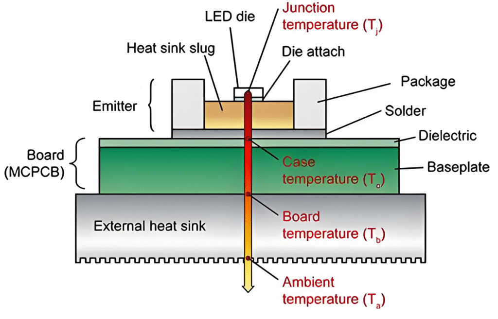
In simple terms, thermal resistance refers to the ability of a material or component to resist the flow of heat. In LED lamps, it describes how efficiently heat moves from the LED junction (the point where light is generated) to the surrounding environment.
- High thermal resistance = Poor heat dissipation → overheating → shorter LED lifespan.
- Low thermal resistance = Efficient heat dissipation → stable performance → extended lifespan.
Since LEDs convert most electrical energy into light but still generate heat, managing this heat is crucial. Poor thermal management not only reduces light output but can also lead to catastrophic failure of the lamp.
The Role of Insulation Class in LED Drivers
LED drivers regulate the power supply to LEDs. Like the lamp itself, drivers are subject to heat buildup. The insulation class of an LED driver defines the maximum temperature at which its insulating materials can safely operate.
For example:
- Class A insulation: Rated up to 105°C
- Class B insulation: Rated up to 130°C
- Class F insulation: Rated up to 155°C
- Class H insulation: Rated up to 180°C
The higher the insulation class, the more thermal stress the driver can handle. Matching the driver insulation class with the thermal resistance of the lamp ensures long-term durability.
Why Thermal Resistance Matters
1. Performance Stability
High temperatures cause luminous flux depreciation — LEDs lose brightness over time. Optimized thermal paths maintain steady light output.
2. Extended Lifespan
Every 10°C rise in junction temperature can halve an LED’s lifetime. Keeping thermal resistance low maximizes lifespan.
3. Energy Efficiency
Excess heat increases driver load, wasting energy. Proper thermal management improves efficiency and reduces power bills.
4. Safety Compliance
LED lamps must comply with international standards (such as IEC 60598 for luminaires). Effective thermal resistance helps meet safety regulations.
5. Consumer Satisfaction
No consumer wants a lamp that dims, flickers, or fails early. Thermal optimization ensures reliable, high-quality lighting experiences.
Key Factors Affecting Thermal Resistance
Several factors determine the thermal resistance in LED lamps:
- LED Chip Design: Larger chips usually dissipate heat more effectively.
- PCB (Printed Circuit Board): Materials like aluminum PCBs improve heat transfer compared to fiberglass.
- Thermal Interface Materials (TIMs): Pastes or pads that fill microscopic air gaps between components, enhancing heat transfer.
- Heatsink Design: Surface area, material, and airflow around the heatsink all matter.
- Luminaire Enclosure: Enclosed fixtures can trap heat, raising overall thermal resistance.
Measuring Thermal Resistance in LED Lamps
Engineers measure thermal resistance (Rθ) in units of °C/Watt. The calculation is straightforward: Rθ=Tj−TaPRθ = \frac{T_j – T_a}{P}Rθ=PTj−Ta
Where:
- Tj = Junction Temperature (°C)
- Ta = Ambient Temperature (°C)
- P = Power Dissipated (W)
Lower values indicate better thermal performance.
Thermal Resistance in LED Lamps vs. Traditional Lighting
Unlike incandescent bulbs, where most energy escapes as heat, LEDs operate at lower wattages and require precision heat management. CFLs and fluorescent tubes distribute heat across a larger surface, while LEDs concentrate it at the junction — making thermal resistance a far more critical issue for LED technology.
7 Proven Optimization Strategies for Thermal Resistance
1. Select the Right LED Package
Use LED packages with optimized chip size and integrated thermal pathways.
2. Upgrade PCB Materials
Switch to metal-core PCBs (MCPCBs) for improved conductivity compared to standard FR4 boards.
3. Improve Thermal Interface Materials
High-quality TIMs reduce air gaps and ensure efficient conduction from the LED to the heatsink.
4. Design Efficient Heatsinks
- Use aluminum or copper.
- Increase surface area with fins.
- Ensure proper airflow.
5. Optimize Driver Insulation Class
Match driver insulation with thermal loads to prevent premature driver failure.
6. Enhance Luminaire Design
- Avoid fully enclosed housings.
- Ensure ventilation or active cooling (fans, liquid cooling for high-power LEDs).
7. Continuous Testing and Validation
Regularly measure junction temperatures to ensure thermal resistance remains within target limits.
Case Study: Thermal Resistance in High-Power LED Lamps
Consider a 50W high-bay LED lamp. Initial prototypes with FR4 PCBs exhibited thermal resistance values exceeding 6°C/W, leading to rapid lumen depreciation.
After switching to MCPCBs and redesigning heatsinks, thermal resistance dropped to 2.5°C/W. As a result:
- Lifespan increased by 40%
- Lumen maintenance improved significantly
- Driver failures reduced by 25%
This example highlights how small design choices drastically impact long-term performance.
Future Trends in Thermal Management
Emerging innovations aim to reduce thermal resistance even further:
- Graphene-based TIMs for ultra-high conductivity
- 3D printed heatsinks tailored for airflow patterns
- Liquid cooling systems for industrial high-power LEDs
- Smart thermal sensors integrated into LED drivers
External Resources
For deeper technical insights:
Conclusion
Thermal resistance in LED lamps is more than an engineering concept — it’s the cornerstone of reliability, efficiency, and safety in modern lighting. By understanding how heat flows through LED components and optimizing every stage of the thermal path — from chip to driver to enclosure — manufacturers can deliver lamps that live up to consumer expectations.
For engineers, the challenge is balancing design, cost, and performance. For consumers, the benefit is clear: brighter, longer-lasting, and safer LED lighting.
Optimizing thermal resistance today not only improves current LED performance but also lays the foundation for the future of energy-efficient illumination.